A bit of background
Linearizing film output was a common prepress practice during the old film to plate era. As a result, a halftone dot in the film corresponds to a distinct tone request in the original file. Therefore, a 50% tone in the file became a 50% tone in the movie, for instance. The preferred interchange file format for prepress tradeshops, publishers, and printers was linear film. At that time, there was no measurement of the plate's final tone. Instead, the presswork's tone was tested in relation to the linear film that was provided and then either determined to be in specification or not. For instance, at 133 lpi, a tone of 50% in the film that results in a tone of roughly 71% in the presswork would be regarded as meeting specification. Surprisingly, despite the fact that the film was linear, the final plates weren't linear because of how exposure changed in the vacuum frame.
Film was no longer an intermediate after the introduction of CTP in the late 1990s. Tone value measurements on the plate thus evolved into a process control metric. However, CTP plates seldom respond linearly to laser exposure, and if a tone reproduction curve is used to make them linear, the resulting presswork is typically too "sharp" — failing to achieve sufficient dot gain — as a result.
Printers started using sharper halftone screens, such as FM screens, at the same time that CTP was quickly gaining popularity. These screens had very different dot gain characteristics than the previous published specifications. In order to obtain the appropriate tone reproduction on press, printers started to take use of the flexibility that CTP offered by applying several tone reproduction curves to their CTP plates.
The printer's decision then is whether to apply a curve to linearize the plate in prepress first, and then, if necessary, apply a second curve on top of the first to get the desired final press tone response.
I was shocked
I asked a question on an online printer's forum: "Do you linearize your plates before applying a press curve (a two curve workflow, for example, one to linearize the plate followed by another one to compensate for dot gain), or do you only apply a press curve to the uncalibrated plate (a one curve workflow, for example, one to compensate for dot gain)?" I wanted to make sure that the approach I had been taking for the past 13 years was the industry standard.
I was astonished by the responses: 70% indicated they just applied a press curve to the uncalibrated (natural state) plate, whereas only 30% said they first linearized the plate with a curve and subsequently did so.
70% of the time using curves on top of curves? That has absolutely no sense to me.
In a vacuum frame, linear film is exposed to the plate in a film to plate operation. The purpose of the plate exposure is to establish a sturdy halftone dot on the plate that will keep its integrity on press, as well as to reproduce the halftone dots in the film as consistently as possible over the surface of the plate. The dynamics of exposure in the vacuum frame cause the final plates to be nonlinear even if the film may be linear. When utilizing negative film in North America, there is often a 2%–5% dot gain on plate at 50% (i.e., 50% in the film produces around 54% on the plate), however when using positive film in Europe and Asia, there is typically a 2%–5% tone loss at 50%.
The key to a successful CTP workflow, just as a successful film to plate workflow, is to tune laser exposure and processing (or lack thereof) to the manufacturer's recommendations. This will produce a solid halftone dot on the plate that keeps its integrity on press. The resulting plates are often not linear because to the dynamics of laser exposure, unique plate features, and processing, just like with a film approach.
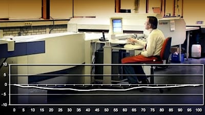
After the engineer has set up exposure and processing for the most robust dot feasible, the thick line that falls below the 0 line in this case represents the natural uncalibrated plate curve.
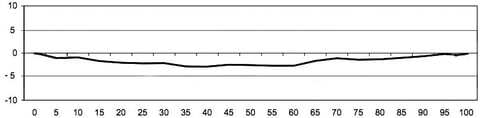
The uncalibrated plate curve with this specific positive thermal plate yields a negative value through the tones. The requested tone values in the file are represented by the bottom numbers in the diagram: 5%, 10%, 20%... 90%, 100%. Linearity is represented by the "0" line. For example, if the plate were linear, the 0 line would be perfectly straight and represent the "plate curve." However, in this instance, a 50% request has yielded roughly a 47% on the plate. A properly exposed CTP plate does not have a linear response, which is rather usual (i.e. a straight line). Also take note that there is no symmetry, making it a typical non-classical Bell curve. Each CTP/plate combo will have its own distinctive natural curvature.
A tone reproduction curve may always be used to generate whatever tones are necessary on plate, including linearizing the plate, therefore from a CtP vendor engineer's perspective, it makes no difference whether the configuration they used results in a linear plate or not. The exposed dot must be reliable, and plate imaging must be uniform across the plate and repeatable from plate to plate.
In other words, the essential requirement is that the plate exhibit a distinctive non-linear tone response when appropriately configured. And it's okay as long as the plate reacts consistently, that is, by delivering the same non-linear tone response each time, because it's impossible to construct any tone reproduction curves without consistency.
Some definitions
Although not "official," these definitions help to make the topics and discussions more understandable.
A "plate curve" is a tone reproduction curve that is added to a plate throughout the workflow so that it can render tone values that are different from those it produces when the laser exposure and processing (or lack thereof) are set according to the manufacturer's specifications. As a result, using a plate curve to linearize an inherently non-linear plate is an illustration of its application.
A "press curve" is a tone reproduction curve that is applied to a plate throughout the workflow so that it can render the tone values necessary to produce a certain tone response on press. It is assumed that the manufacturer's requirements have been followed while setting up the laser exposure and processing (or lack thereof).
According to this definition, a linearizing curve is a press curve if it is the only one used since a linear plate is required to produce the desired tone response on press.
In this context, a plate curve is unrelated to tone reproduction on a press. It functions as a calibration curve in essence. It returns the plate to a stable state. The setting of the manufacturer's processing chemistry, processing time, and laser exposure intensity, however, efficiently calibrates the plate plate to a known condition in a CtP environment. Even though it may not be linear, it is known. Applying a plate curve to what has already been calibrated eliminates the need to recalibrate.
A different perspective on the query
Assume for the moment that the tone response we require on press was delivered by a linear plate. Then, would it make sense to utilize two curves—one to linearize the plate (a plate curve) and the other to linearize the linearized plate (a press curve)? I have my doubts. Based on the plate's uncalibrated natural state, it makes more logical to only use one linearizing curve.
If that reasoning is sound, why wouldn't it also be sound if we required a non-linear press curve? Utilize only the single non-linear press curve that is based on the plate's uncalibrated natural non-linear condition.
Press curves can be constructed using the tone response of the plate as long as it is consistent. However, both the use of press curves and the use of linearizing plate curves will be unsuccessful if the plate exhibits inconsistency in its tone response. Curves, plates, or presses cannot be used on an inconsistent instrument.
What the "authorities" have said "
6.2 Origin of NPDC curves
G7 research examined multiple press runs using ISO-standard ink and paper as well as a range of plate types imaged on "un-calibrated" CTP systems (no RIP curves applied, not even to "linearize" the plate) to ascertain the "natural" NPDC curves of commercial CTP-based printing.
5.4 Set up the RIP
Set up the plate making RIP as you normally would for a job, but make sure to remove any values from the calibration table that are currently in use or start over with a new, empty table. It is ideal to use "un-calibrated" plates for the initial press run, meaning there should be no calibration values in the RIP.
NOT linearizing the plate-setter to ensure that measured dot values on the plate precisely match original file percentages is crucial. Contrary to popular opinion, this might make the following stages less accurate.
We can provide you with better pricing because we are a direct manufacturer. Please feel free to contact us, ask any questions by leaving a message below.